I started putting up backdrop last week with the goal to complete the upper level backdrop around the room by the end of this weekend. Before the backdrop can go up, I needed locate a few key elements which required refining the conceptual plan.
One of the more complicated locations of the layout is Phillips. It is complicated because Phillips itself is complicated and because the room complexities. I’ve allocated 25′ for Phillips, but it must bend under the stairs and past the entrance door to the railroad. Both ends of the 25′ must turn around walls.

Above is the conceptual diagram of Phillips. The complexities stairs and entrance are apparent. I used the stairs to my advantage to bend the layout in as the prototype bends. The diagram shows the refined locations for Salmon Hole and Covered bridges.
There are several key refinements I wanted to locate.
- Salmon Hole Bridge, as backdrop and layout support must be lower at the bridge. I had been struggling if the bridge should be parallel to the wall as shown or angled in the corner. In the end, I chose parallel to the wall. The benefit is it will make it seem further from Strong to Phillips but the disappointment is that the siding in front of the toothpick mill will be shorter, too short to hold a train and I loose the long fill between bridge and mill.
- Backdrop directly under the stairs. The stairs are outside the room, but the layout goes under them. The backdrop will not be full height below the stairs, the higher the backdrop, the more Phillips must extend out into the room. To far into the room impacts isle space and can conflict with Kingfield and the winter store.
- The Phillips covered bride had to be located for support and lower backdrop requirements.
Here is the 1916 ICC map for Phillips main yard and that was my primary focus to mockup.

Phillips ICC map. The covered bridge as at the far right. The bend in Phillip is great for an inside corner of a room, or in my case an outside corner so I can operate from the west side of the tracks as works best for most other locations on the SR&RL, specifically Strong and Farmington.
While one can work everything out in CAD, that does not prove that it will work to the eye. To satisfy my need for visual comfort I reviewed images of my old layouts (reused the same Phillips sections) and mocked it up in place.
Here’s the old layout. The sections no longer exist the standards were tighter than I wanted on my future layouts (one I’m building now 15 years later).

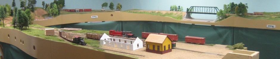
Taken during a 2005 NMRA National Convention ops session, this image shows the South end of Phillips yard. This simple layout fit on two 5 foot long sections and operated just fine. This version of Phillips had #6 turnouts and 32″ minimum radius. Hopefully even with #8 turnouts and 36″ minimum radius I can capture this same simple feel.

Here is the far end of the yard, again during a 2005 NMRA Convention ops session. The turntable and engine house never got built, but they would fit. The yard kept one operator active all night. This image shows how easy it was capture the feeling of Phillips even after omitting some of the lesser aspects.
Here is the mockup for the new layout. Simply laid out with foam.

Phillips mockup. The first track track to the left is the Brayman track and the second goes to the turntable. The board represents the turntable and that is followed by a cutout of the Kingfield engine house (sufficient visual substitute). The rest of the yard bends to the right.

Close up of the turntable location and engine house. The yard turns off behind. The track to Wilbur store will just curve around the backdrop support. The yard would continue onto the second piece of foam and onto the Covered Bridge. The mockup for the Covered Bridge can be seen in the distance. The curves are laid out using fast tracks sweep sticks
Al Churella and I have discussed operations in Phillips. On his layout he indicates that the Brayman track was probably used for sorting cars. Ever since that conversation I’ve hoped to include it on my layout. The Brayman track track was quite long, mine might only be 2-3 feet long, but just that short length will be useable to sort cars and build trains. Similarly, I think the Wilbur track was used for sorting cars.
The Fast Tracks sweep sticks are great for laying out track. They are designed to fit between the rails of flex track to hold that track at a specific radius. I bought a bunch of 36″ radius (my minimum radius) so that I could assemble a 180 degree curve (required for the peninsula. Additionally, I purchased a couple 32″ and 34″ radius just in case I need a tighter radius. Even better I got some larger radius that I can use for easements.
What I find best about the sweeps is holding them up to see what curve will fit in a specific space. I also plan to hold them up as I bend roadbed to make sure I do not put in kinks or make the roadbed too tight. I think they are worth the cost.
Here’s a link to HOn3 36″ sweeps or Sn2 36″ sweeps. The only difference is the laser cut letter. Click around to find the sweeps that are right for you. They come in various scales and gauges.

Phillips will extend beyond the entrance. You can see the turnout for Brayman track. The points on that turnout will be on a fixed portion of the layout. 6-12″ beyond the points will be a drop down. The door is 36″ and I hope to have 30″ for the drop down. This mockup proves that should be possible.
Phillips will cross the entrance. I expect 1/3 will be fixed and 2/3 will be a 30″ drop down. The drop down will be 8″ wide and contain scenery. Most of the time, the drop under will be fixed in the up position. This will result in a 50-52″ clearance duck under. That is plenty for me do duck and swoop under. I’m hoping the clearance will be be a more like 40″ wide, rather than the 30″ of the drop down. I find the wider the duck under the easier it is to swoop under rapidly. The lower deck will also pass under this area. It will have a lift up, which will most often be up, and only lowered for trains crossing.
I could go on and on about Phillips and my thoughts to model it. But this was enough analysis for the installation of the backdrop. Enough diversion, I need to get back to working on the actual installation!


Pingback: 2020 Wrapup | Sn2 Modeler
Looks good Dave. I second your comments on the FT sweeps. I’ve been using them and they really do the job.
Thanks Tom….Open the garage door and we’ll design a Phillips for you too!